
Sensor Range vs Detection Zone: What Matters in Commercial Restrooms?
Look beyond a maximum sensing distance. Coordinate hand recognition, water delivery and basin geometry for a touchless experience that works where people actually wash.
Explore the difference ↓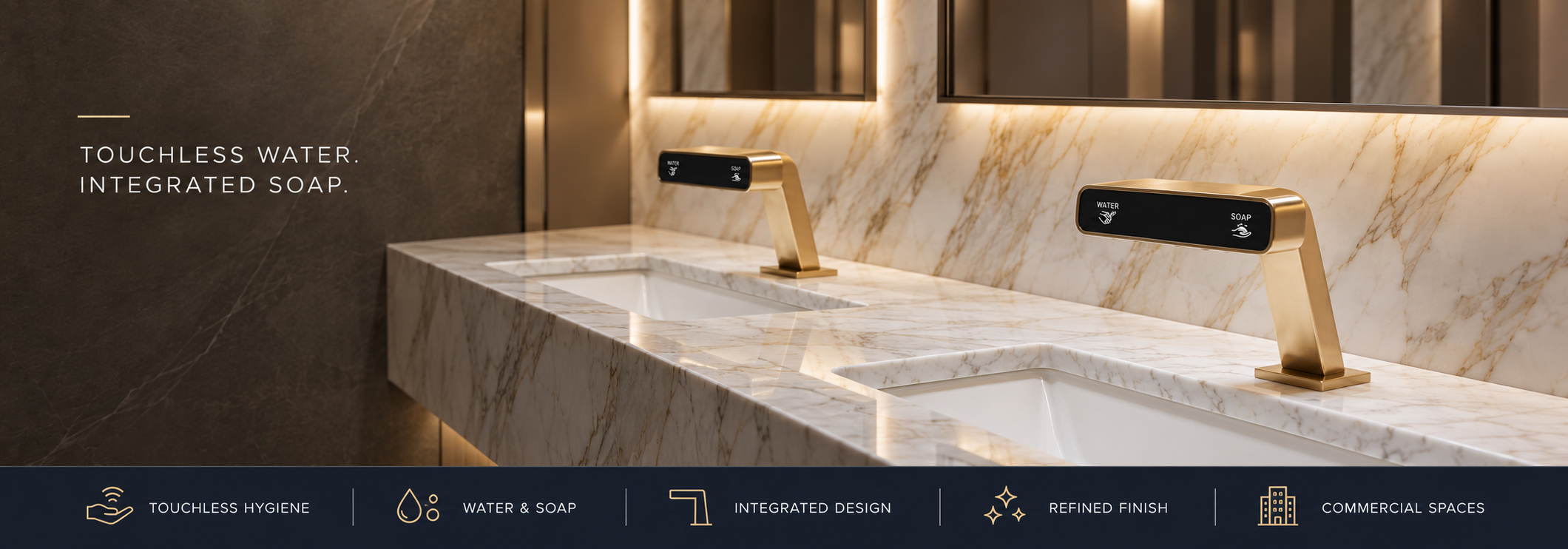
An AEC guide for architects, plumbing engineers, contractors and facility managers
A sensor faucet can meet its published detection distance and still make handwashing awkward. The deciding question is whether the installed sensor reliably recognizes hands where users naturally wash them, inside the basin and beneath the water outlet. That requires coordination between the faucet, lavatory, control settings and finished restroom environment.
Sensor range
How far from the sensor can a suitable target be recognized?
Check: the measurement datum, factory setting, adjustment interval and stated test conditions.
Detection zone
Where can hands be recognized within the installed wash station?
Check: natural hand entry, coverage beneath the outlet and separation from unrelated actions.
- DistanceRecognize hands at the intended position.
- CoverageSupport a comfortable washing area.
- ContainmentKeep sensing and water delivery coordinated with the bowl.
- TimingStart, maintain and stop flow as intended.
Sensor range vs detection zone: what is the difference?
A range figure often expresses how far a suitable target can be detected under stated conditions. Depending on the product, the documentation may identify a factory setting, an adjustment interval or a recommended operating distance. These are different quantities. A maximum adjustable value should not automatically become the installed setting.
The detection zone is the working spatial envelope. Its shape follows the sensor location, optical field, orientation and controller behavior, while the actual installation determines which parts of that envelope are useful. Some manufacturers use “range” and “zone” interchangeably. Read the drawing and programming instructions alongside the marketing description.
| Term | What it describes | What to verify on site |
|---|---|---|
| Sensor range | Detection distance, usually associated with a target and sensor axis. | Whether the stated distance is a preset, limit or operating interval. |
| Detection zone | The area or volume in which targets can be recognized. | Whether normal hand positions lie within usable coverage. |
| Field of view | Angular coverage of the sensing optics. | Orientation and off-axis behavior, where documented. |
| Minimum detection distance | A possible near limit below which reliable recognition is not assured. | Very close hand positions, without assuming all sensors have the same near limit. |
| Activation and release timing | When a valid detection starts flow and when departure stops it. | Perceived delay, continuity while rinsing and the documented shutoff behavior. |
| Maximum run time | A controller limit for a prolonged activation. | The selected timeout and the procedure for restoring normal operation. |
Procurement question: “Where is the distance measured from, what target was used, and what adjustment method applies to this exact faucet and controller?” A product listing that supplies only a distance leaves those coordination questions unanswered.
Why a longer sensor range can change the whole zone
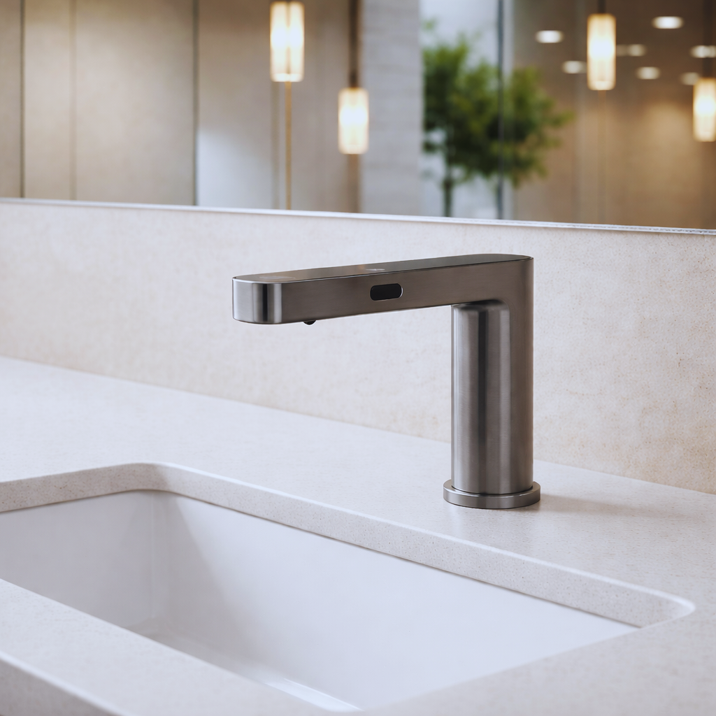
Evaluate the overlap between hands, water and bowl.
The sensor field and water stream have separate geometries. A hand may trigger the faucet at one position, then leave usable coverage when moved under the outlet. Conversely, a sensing field that extends beyond the bowl can include objects unrelated to washing.
For a simple, symmetric angular field, the geometric width increases with distance. This explains why extending range can also expose more lateral space. Real activation boundaries depend on the sensor and controller; they are not guaranteed to form a perfect cone.
Illustrative field width = 2 × distance × tan(half-angle)Using an assumed 30° full angle, the mathematical width is approximately 54 mm at 100 mm distance, 107 mm at 200 mm, and 161 mm at 300 mm. These values illustrate geometry only. They are not recommended faucet settings or measured product performance.
A useful mock-up should establish the overlap between the recognized hand positions and the part of the bowl that safely receives water. If that overlap is poor, changing a range value alone may not resolve the mismatch. A different spout reach, mounting position or sensor configuration may be necessary.
Reflective infrared and time-of-flight: ask what the faucet actually uses
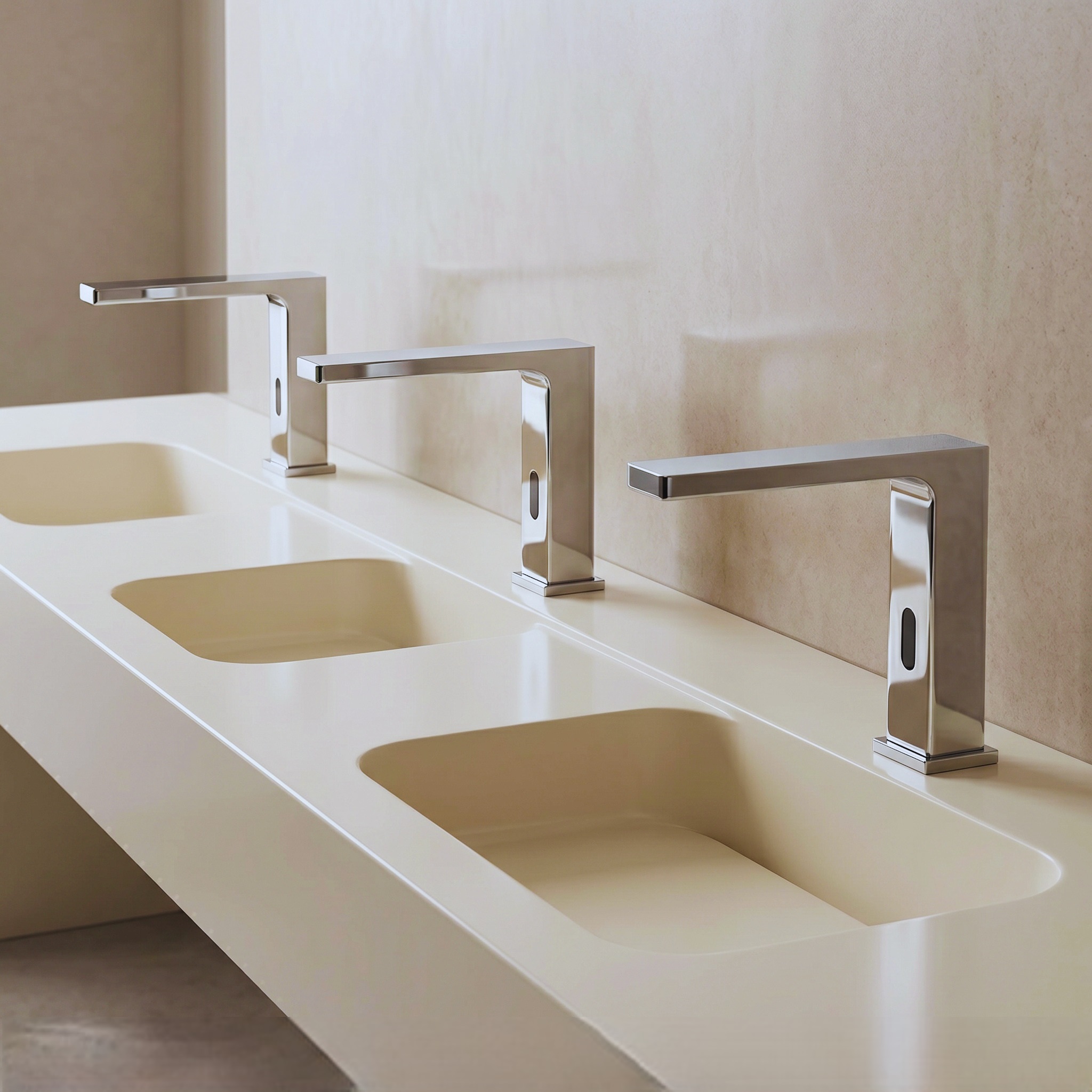
Active reflective infrared
The emitter sends infrared light toward a target and the detector receives a reflected signal. Sloan describes this arrangement for many of its faucets and notes that the returned intensity varies with surface reflectivity. In practice, target position and the surrounding finishes deserve attention. Sloan source ↗
Optical time-of-flight
Time-of-flight sensing estimates distance from light travel time. It can also use infrared light: “IR” and “ToF” are not mutually exclusive descriptions. ST’s VL53L1X documentation illustrates a sensor with a defined field of view and a programmable region of interest. ST source ↗
Controller decisions
Detection is only part of operation. The controller also determines flow behavior, timeout and supported adjustment options. American Standard’s Selectronic remote supports range and timeout adjustments on compatible amber-sensor models; compatibility must be checked. American Standard source ↗
A component specification is not a faucet specification. A sensor’s theoretical capability does not establish the performance of a finished fitting with its lens, cover window, firmware and mounting geometry. ST’s documentation is useful for understanding the technology; it does not establish which chip a particular faucet contains.
Avoid selecting solely on a technology label. Ask the manufacturer to identify the sensing method, adjustment limits, commissioning procedure and supported installation conditions. Then evaluate the complete assembly in the intended wash station. Do not assume a touchless commercial faucet works like a passive room-occupancy sensor or requires continuous hand movement.
The faucet-and-basin relationship matters more than an isolated distance
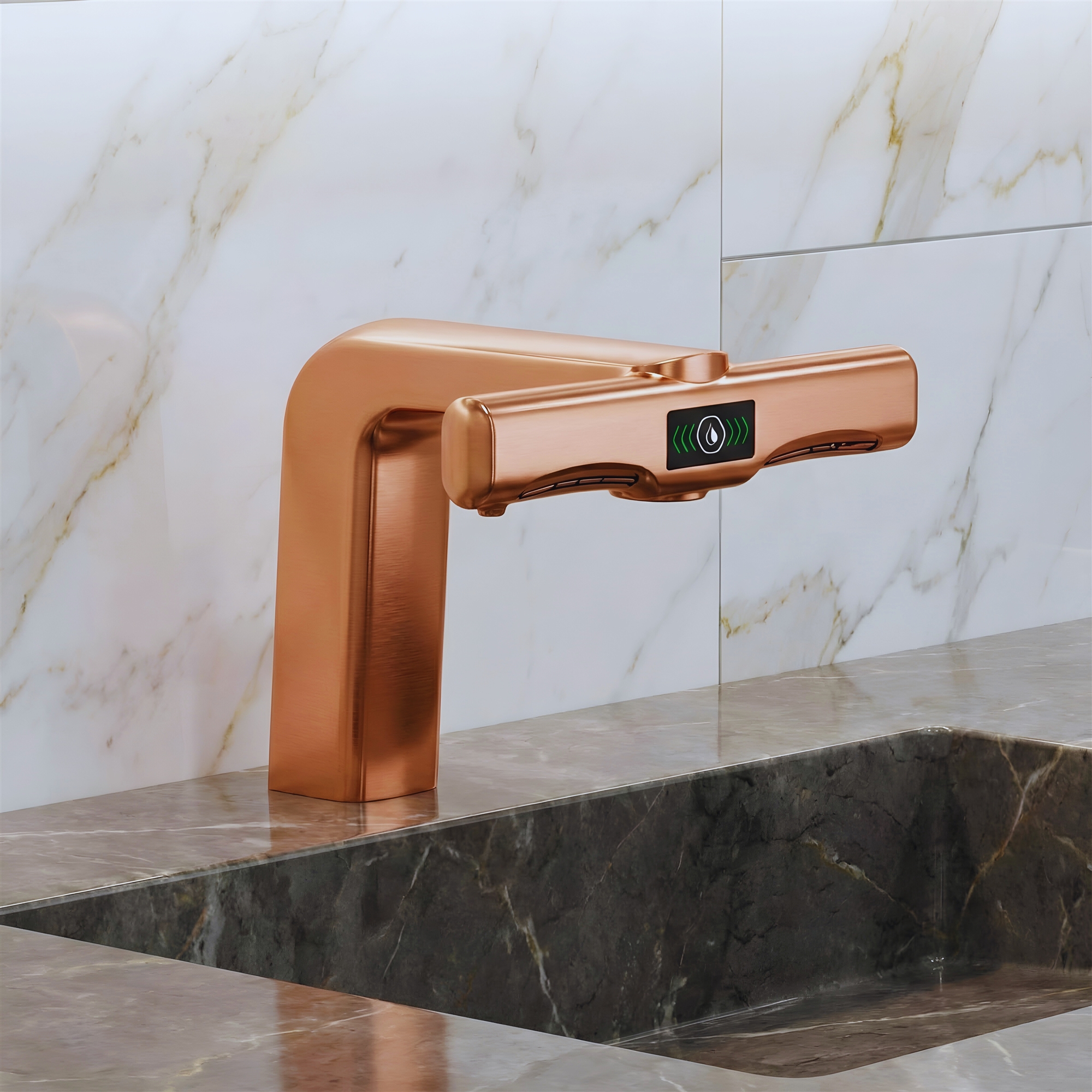
A commercial touchless faucet should be selected with its lavatory, rather than treated as a finish choice added after countertop dimensions are fixed. The sensor window may be located in the body, near the outlet or in another position. That location changes the relationship between hand approach and water delivery.
Mark the proposed sensor axis, outlet location and usual rinsing position on the coordination drawing. Include the front edge of the counter, basin interior and soap-dispenser nozzle. This makes an interface conflict visible before it becomes a complaint from restroom users.
Specify the pairing at submittal.
Keep the selected faucet, basin and accessory arrangement together in the approval record. If the basin changes after approval, review sensing and splash containment again. A faucet substitution should trigger the same check even when its mounting hole and finish appear equivalent.
-
Spout reach and outlet height
Watch for: The comfortable rinsing position and recognized hand position do not coincide.
Coordinate: Check both positions in section and in a working mock-up.
-
Basin depth and profile
Watch for: Hands must move unusually low, rearward or close to a surface to obtain flow.
Coordinate: Test realistic washing movements across the bowl.
-
Sensor location and direction
Watch for: The user approaches outside usable coverage.
Coordinate: Confirm the sensing window’s position on the exact selected fitting.
-
Countertop and backsplash finishes
Watch for: The sensor faces a background that differs from the tested installation.
Coordinate: Include actual finish samples and final splashbacks in the trial.
-
Soap dispenser and accessories
Watch for: Reaching for soap or a towel also places hands in the faucet’s zone.
Coordinate: Test water-only and soap-only actions separately.
-
Adjacent stations
Watch for: A hand reaching between fixtures activates the wrong station.
Coordinate: Test neighboring units together with the final spacing.
Reflectivity, sunlight and obstruction can change detection behavior
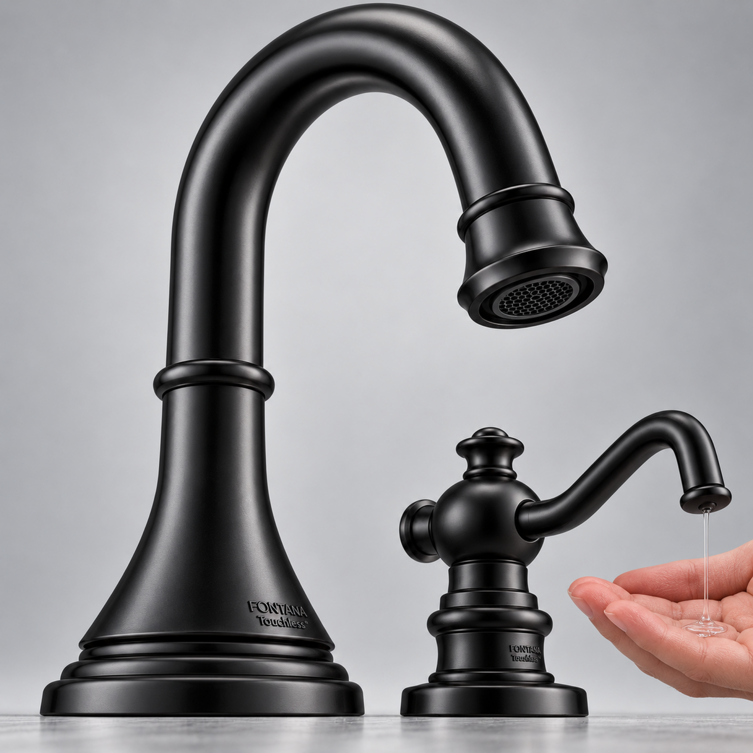
FontanaShowers’ sensor-coordination resource identifies reflective surfaces, direct sunlight and obstructions as installation considerations. Its recommendations also distinguish faucet and soap-dispenser sensing fields. FontanaShowers source ↗ Use these variables as prompts for a project-specific trial rather than assuming every restroom finish will produce the same result.
Test the actual background
Retain the approved basin and counter finish during the trial. Check the installation with the bowl dry and wet, and observe whether a fixed background causes a repeatable nuisance event. Record the condition before adjusting the system.
Check relevant lighting conditions
If daylight reaches the vanity, repeat checks when it reaches the sensing window. Record the time, blind position and lighting state. One successful evening test may not represent the next morning’s environment.
Keep the optical path available
Coordinate accessory positions and removal of installation packaging before acceptance. Follow the manufacturer’s lens-cleaning instructions. Use a clean sensing window as the baseline when investigating a new fault.
Distinguish overlap from interference
A hand inside two zones can legitimately trigger two devices. That observation alone does not prove optical interference. Test each device separately, then together, before attributing the event to electronic crosstalk.
Touch-free activation should work from the accessible approach
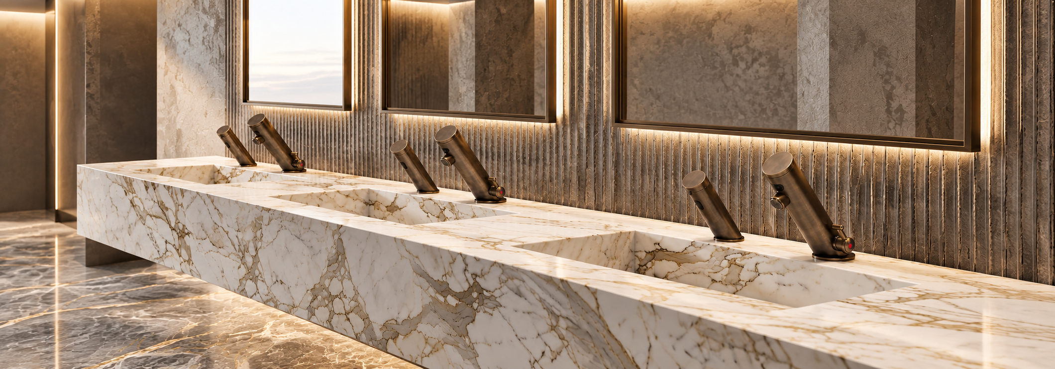
The U.S. Access Board’s lavatory guide addresses forward approach, knee and toe clearance, reach, faucet operation and protection from exposed plumbing. It distinguishes touch-free controls from manual metering controls: motion-activated faucets do not have the same minimum activation-duration requirement. U.S. Access Board source ↗
Project recommendation: evaluate hand recognition from the intended seated approach as well as from standing positions. Check that the usable washing area can be reached comfortably and that under-counter controllers or enclosures preserve the required clearances. A product’s accessibility claim should be reviewed with the complete installation.
Test ordinary handwashing movements
Check entry, wetting, hand rotation and rinsing. A user should be able to find and maintain flow without repeatedly searching for a small activation point. Record the positions that cause an interruption rather than simply reporting that the faucet “works.”
Support the full washing sequence
CDC guidance includes wetting, lathering, scrubbing for at least 20 seconds, rinsing and drying. That scrubbing recommendation does not prescribe 20 seconds of continuous faucet flow. Coordinate soap, water and drying access as separate tasks within one usable station. CDC source ↗
What FontanaShowers, BathSelect, Moen, TOTO and American Standard show
Manufacturer resources demonstrate why a single “best sensor range” is a weak procurement rule. Use the examples below to identify the documentation and questions needed for a particular project. They describe published guidance for specified resources or product families; they are not comparative test results.
FontanaShowers
Its coordination drawing describes a 50–200 mm faucet operating range and an approximately 40° detection cone for the illustrated set. FontanaShowers source ↗
Ask at submittal: Does the selected model use the illustrated configuration, and how is its sensor aligned with this basin?
BathSelect
Its temperature-control touchless-faucet guidance states that sensor platform, range, adjustment and response can vary by model. BathSelect source ↗
Ask at submittal: Which current specification and installation manual apply to the exact faucet, controller and power package?
Moen M-POWER
Moen’s distance-setting video explains customization of the factory sensing distance on the demonstrated M-POWER faucets. Moen source ↗
Ask at submittal: Which adjustment sequence applies to the supplied model, and what settings should facilities staff retain?
TOTO
Installation manual 0GU3076 describes automatic range adjustment after sensor connection, with the area kept clear; the process may take up to 20 seconds. TOTO source ↗
Ask at submittal: Does the selected faucet use this initialization process, and has it been completed with the finished basin unobstructed?
American Standard
Its Innsbrook Selectronic support article specifies a 2–10 in. adjustment interval and a 6 in. factory setting for the faucets covered by that article. American Standard source ↗
Ask at submittal: Is the submitted faucet covered by that guidance, and which setting suits the approved basin pairing?
Keep model boundaries visible: the figures above apply to the cited examples. They should not be copied across an entire brand or used as installation settings for an unrelated faucet.
A commissioning sequence that tests the working zone
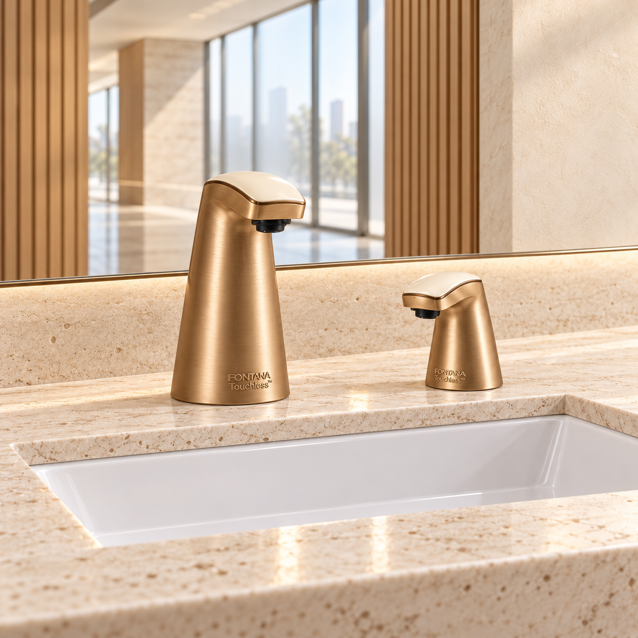
The following sequence is an editorial project workflow. Agree acceptance criteria with the design team and manufacturer before testing; the workflow does not establish a universal code tolerance or substitute for the product instructions.
Start with the approved installation and a known control setting. Make one documented change at a time. If several parameters are changed together, it becomes difficult to identify which change improved activation or introduced a new problem.
Assign the record to a physical station.
Use the room and fixture identifier, not just the product SKU. Two identical faucets can have different lighting, accessory positions or basin interfaces. Keeping a station-specific record makes later service more precise.
Jump to the acceptance record →-
Confirm the installed assembly
Record the faucet and controller models, basin reference, outlet arrangement, power source and accessories. Compare the installation with the approved submittal. Resolve changes in spout position, basin or sensor configuration before tuning.
-
Complete the maker’s startup procedure
Follow the specified initialization or calibration sequence. Keep the area clear when instructed. Remove tools and packaging first, and wait for the documented completion indication before presenting a hand. Avoid importing a reset sequence from another model.
-
Map useful hand positions
Test front entry, one hand, two hands and movement beneath the outlet. Include the intended seated approach where relevant. Record the near and far usable positions from a clearly identified datum; note whether they are measured or estimated.
-
Challenge unintended activation
Test reaching for soap, using the adjacent station and passing the wash station without presenting hands for washing. Identify the action that caused flow. Separate a shared hand position from a suspected optical interaction between devices.
-
Verify flow behavior
Observe the time to first water, flow continuity while rinsing, release after hands leave and the documented prolonged-activation timeout. Check the actual operating mode. A metered cycle, release delay and protective timeout perform different functions.
-
Retain settings and retest changes
Save the final permitted settings and observations. Verify the documented behavior after any approved power-restoration test. Recheck if accessories move, the basin changes or a new lighting condition is reported. Hand over the applicable manual with the station record.
For repeat testing, define the number of attempts, approach positions and observation period in advance. Report successful activations against total attempts and nuisance events against the recorded observation time. Those denominators make the result useful without implying that a short trial proves lifetime reliability.
Commercial sensor-faucet commissioning checklist
Use one record per wash station. Add project-specific pass criteria and record the actual result, final setting and any corrective action.
| Check | Test condition | Evidence to retain |
|---|---|---|
| Assembly identity | Faucet, controller, basin and power package match the approved pairing. | Model references, station ID and relevant manual revision. |
| Hand recognition | Normal hand entry and rinsing positions, including relevant user approaches. | Attempt count, misses and locations of interruptions. |
| Water containment | Hands remain within the bowl beneath the outlet. | Usable hand positions and observed splash behavior. |
| Accessory separation | Soap-only, towel-only and neighboring-station actions. | Any action that caused unwanted faucet flow. |
| Background conditions | Finished surfaces, clean sensor window and relevant lighting states. | Lighting, bowl condition, date and observation period. |
| Flow control | Entry, hand removal and the manufacturer’s prolonged-activation test. | Operating mode, observed timings and selected timeout. |
| Power restoration | Authorized test using the specified power-restoration procedure. | Settings retained or initialization required, as documented. |
| Service readiness | Access to permitted adjustments, controller and maintenance items. | Final settings, access arrangements and facilities handover. |
Suggested record fields: room/station ID; faucet/controller model; basin model; power source; setting before and after adjustment; lighting state; hand positions tested; successful attempts/total attempts; nuisance events/observation time; corrective action; responsible person; date.
Missed detection and no water flow are different faults
A no-flow complaint should first be classified by observed behavior. Does the sensor acknowledge the hand? Does the control system report a fault? Is the failure repeatable at one position or present everywhere? A sensor-range change cannot correct every hydraulic, power or control problem.
- Flow only at one awkward hand position
-
Investigate: Coverage and outlet alignment.
Next check: Map recognized positions and compare them with the rinsing position.
- Activation during soap use
-
Investigate: Hand approach and overlapping zones.
Next check: Repeat the soap-only action; review accessory placement and supported settings.
- Interruption during rinsing
-
Investigate: Hand position, operating mode or release behavior.
Next check: Observe the hand path and consult the controller’s documented mode.
- Issue only under one lighting condition
-
Investigate: Environment-dependent sensing.
Next check: Reproduce and record that lighting state before making adjustments.
- Detection indication but no delivered water
-
Investigate: Supply, restriction, valve or control output.
Next check: Follow the manufacturer’s hydraulic and electrical diagnostic sequence.
- No indication where one is expected
-
Investigate: Power, connection or sensing fault.
Next check: Use the model-specific diagnostics; do not assume another model’s LED meanings.
Record timing as well as position. Water that continues briefly after hands leave may reflect an intended release delay; repeated flow with an empty station requires a different investigation. Compare the event with the applicable instructions before deciding that the sensor is defective.
Unwanted activation affects water use even with a low-flow outlet
Sensor performance and flow regulation should be reviewed together. A low-flow outlet limits delivery rate, while unwanted activations add operating time. Neither the word “touchless” nor a long detection range establishes a project’s water savings.
Calculate the event volume
Event volume = flow rate × duration ÷ 60For an illustrative constant flow of 0.5 GPM, an unwanted 6-second activation delivers 0.05 gallon, about 0.19 liter. If 1,000 such events occurred, they would total 50 gallons, about 189 liters. These are arithmetic examples, not measured site consumption.
Apply the correct faucet category
EPA currently has WaterSense labeling criteria for private lavatory and bar sink faucets, but not public lavatory or metering faucets. Its guidance identifies 0.5 GPM or less for efficient public lavatory faucets. Verify the applicable adopted code and exact outlet configuration for the project. EPA source ↗
When reviewing a water-use log, separate normal handwashing, cleaning and documented purge functions from unwanted user-independent events. Otherwise an intended maintenance cycle can be mistaken for a detection fault. Use measured flow where available and describe any estimate clearly.
What to ask before approving a commercial touchless faucet
Request the current installation manual and a coordinated faucet-and-basin drawing before approving appearance or maximum sensing distance alone. The response should identify the sensing-window location, available adjustment method, supplied power package, operating mode and access to serviceable controls.
Define the interface
Show the mounting datum, spout outlet, sensor window, basin section and nearby dispenser. Identify any manufacturer limitations on placement or exposure.
Define permitted settings
Identify the factory values, supported adjustments and model-specific startup sequence. Confirm who can change settings and which tools are required.
Define acceptance evidence
Agree the washing positions, unintended actions and operating conditions to test. Require a retained record of the approved settings and observed results.
Suggested specification intent: “Demonstrate reliable activation within the intended handwashing area of the approved faucet-and-lavatory assembly. Verify normal user approaches, continuity during rinsing, documented shutoff behavior and separation from adjacent accessory use. Record final supported settings and resolve observed nuisance activation before handover.” This is project language to adapt, not a published product certification.
Sensor range and detection zone FAQs
What is the best sensor range for a commercial restroom faucet?
The best installed setting depends on the selected sensor, spout, basin and intended hand approach. Start with the applicable manufacturer guidance, then verify the usable washing area and unwanted actions. There is no single range value established by the sources in this guide for every commercial restroom.
Does a longer range mean a better touchless faucet?
A longer available range can support some geometries, but it can also include more space outside the intended washing area. Compare whether users can obtain and maintain flow comfortably and whether adjacent actions cause unwanted activation. Judge the installed assembly against the project’s requirements.
Are infrared and time-of-flight two completely separate technologies?
No. Optical time-of-flight sensors can use infrared light. A useful distinction is between a reflective system’s signal-processing method and a system that estimates distance from light travel time. Confirm the finished faucet’s architecture and settings rather than inferring them from “IR” or “smart sensor” language. ST source ↗
Can a faucet activate when someone reaches for soap?
Yes, if that hand movement enters the faucet’s recognized area. Test the soap-only action and review the physical arrangement. Treat overlapping hand positions and suspected optical interference as different possibilities; one unwanted event does not identify the cause.
Does ADA require a touch-free faucet to run for at least 10 seconds?
The U.S. Access Board states that motion-activated faucet controls do not have a minimum run duration. The minimum 10-second provision applies to manually operated metering controls. Review the actual control type and the complete accessible installation. U.S. Access Board source ↗
Should calibration happen before the basin and accessories are finished?
Follow the installation instructions, then verify performance in the final configuration. Keep temporary objects clear during any automatic learning sequence. A later change to the bowl, background or accessory location should prompt review of the working zone and any required manufacturer procedure.
Why does water stop even when my hands seem to be under the spout?
The outlet position does not prove that the hands remain inside the sensing zone. Other possibilities include the selected operating mode or a documented run-time limit. Observe the position and timing of the interruption, then use the exact model’s diagnostic instructions.
Which documents should a facilities team keep?
Retain the faucet and controller references, installation manual, basin pairing, power configuration, final supported settings and station-specific commissioning record. Include observed problem conditions and corrective actions so the next technician can reproduce the issue.
Technical references for commercial restroom specification
Use these original sources to verify sensing principles, the scope of published product guidance and the relevant public-agency requirements.
- Sloan — reflective infrared sensing explanation How returned infrared intensity relates to targets and reflective surroundings.
- STMicroelectronics — VL53L1X time-of-flight sensor Component-level explanation of ranging, field of view and region of interest.
- American Standard — Selectronic Remote Control 2.0 Adjustment and diagnostic features for compatible amber-sensor devices.
- FontanaShowers — faucet and soap-dispenser detection zones Illustrated fixture-set coordination, sensing fields and installation considerations.
- U.S. Access Board — Lavatories and Sinks Accessible approaches, clearances, reach and faucet-control guidance.
- CDC — About Handwashing Wetting, lathering, scrubbing, rinsing and drying guidance.
- BathSelect — Temperature-Control Touchless Faucets Model-specific sensor, adjustment and control considerations.
- Moen — M-POWER sensor distance-setting video Manufacturer demonstration of sensing-distance customization.
- TOTO — Installation and Owner’s Manual 0GU3076 Model-specific initialization and automatic sensing-range adjustment.
- American Standard — Innsbrook Selectronic sensor-range support Published adjustment interval and factory setting for the covered faucets.
- U.S. EPA — Bathroom Faucets WaterSense faucet scope and public-lavatory flow guidance.
Evidence basis: this editorial guide draws on manufacturer documentation and U.S. public-agency guidance reviewed on October 10, 2026. The commissioning workflow and geometric examples are proposed design tools, not reported field-test findings. Brand examples do not represent a performance ranking.
Image note: restroom photographs are original AI-generated editorial illustrations and do not depict verified manufacturer products or completed project installations. The sensor diagram is a conceptual drawing, not a scaled product detail.